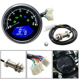
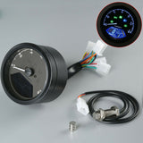
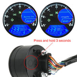
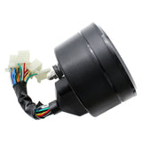
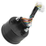
LCD Digital Motorcycle Speedometer Tachometer Cafe Racer moto Odometer 12000RPM
Specifications:
Working Voltage: 8-18V
Rated Voltage: DC 12V
Working Temperature: -20 - +70 Celsius
Storage Temperature: -30 - +80 Celsius
Digital Display Speed Range: 0-199km/h
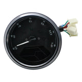
Needle Display Rpm Range: 0-12000rpm
Digital Display Odo Distance Range: 0-99999.9km
Gear Indicator: 1-6
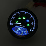
Backlight: Blue
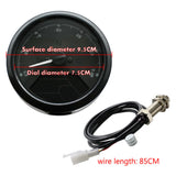
Installation diameter: 9cm
Height: 5.3cm
Cable Length: 12cm
Weight: 344g
Features:
-Large anti -UV & Anti-g lare LCD screen
-All-in-one design with digital signal processing system
-Using chip technology for most of the components
-Multiple indicator functions as the L/R Turn Signal, High Beam, Position Lights, N Lights
-High withstand voltage up to 100V
-Waterproof & Anti-vibration
-Fits for most motorcycle that is with 4 stroke, 2/ 4 Cylinders (default as 1 cylinder of the setting)
Package includes:
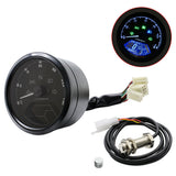
1X speedometer
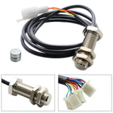
1X magnet
1X wire with a plug and screw
1X instruction manual
Tips: The meter comes with a instruction, if you have any problem please contact us. Will do our best to help you.
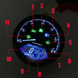
Wire Numbers:
1: Beam indicator Number
2: Neutral gear Number
3: Rotation rate Number
4: High beam Number
5: Turning right Number
6: Oil Level Number
7: Low battery voltage alarm Number
8: Gear Number
9: Mileage accumulation Number
10: Speed Number 11:Turning left
------------------------------------------------
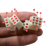
1[Yellow/black]:speed signal wire
2[Blue]:distance light Positive polar connection
3[blue/white]:outline marker lamp Positive polar connection
4[Green]:negative pole(any negative pole or ground )
5[Black]:positive electric door lock connection
6[Red]:positive battery connection
7[Orange]:left signal Positive polar connection
8[Brown/white]:outline marker lamp Positive polar connection
9[Fleet blue]:right signal Positive polar connection
10[Green/white]:negative GR-6 connection
11[Green/black]:negative GR-3 connection
12[Yellow/red]:negative GR-4 connection
13[Yellow/white]:negative GR-5 connection
14[Green/red]:negative N gear connection
15[Pink]:negative GR-1 connection
16[Blue/red]:negative GR-2 connection
17[Red/white]:positive speed sensor connection
18[Black/white]:speed sensor signal wire connection


